Power-off and power-on of high-voltage electrical system

-
Before maintaining any components of the high-voltage electrical system, power off the system according to the following requirements, and power on it after maintenance, unless otherwise specified in the operating procedure.
-
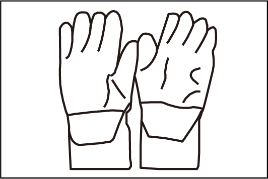
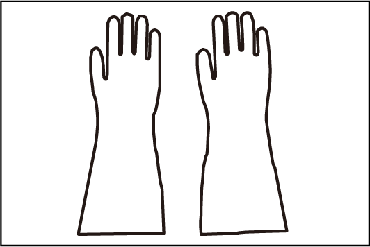
All high-voltage system wiring harnesses of the vehicle are orange. Before maintaining any components of the high-voltage system, take protective measures according to the maintenance requirements of the high-voltage system, such as wearing insulating gloves, insulating shoes and goggles, laying insulating pads, and setting high voltage warning signs.
-
Maintenance operations on the high-voltage electrical system must be carried out by technicians with qualifications recognized by BYD and in compliance with local regulations.
-
Violation against these safety reminders may result in personal injury or vehicle damage.
Personal protective equipment and tools
| S/N | Picture | Name | Description |
|---|---|---|---|
|
1 |
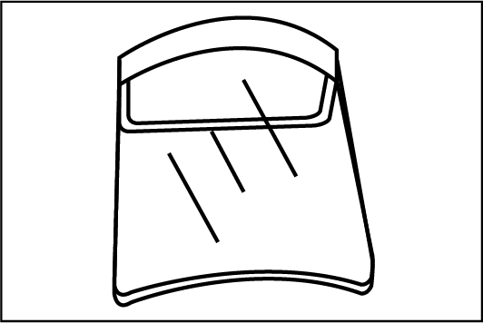 |
Protective mask |
- |
|
2 |
 |
Insulating gloves |
Insulation voltage above 1000 V |
|
3 |
 |
Non-slip gloves |
- |
|
4 |
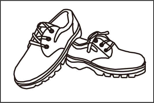 |
Insulating shoes |
Insulation voltage above 1000 V |
|
5 |
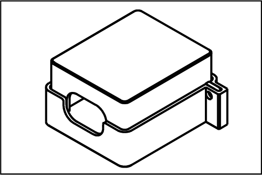 |
Protective cover for high-voltage cable connector |
For protecting the plug and preventing electric shock |
|
6 |
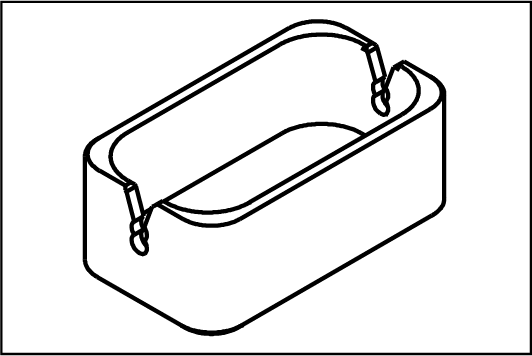 |
Protective cover for high-voltage cable connector |
For protecting the plug and preventing electric shock |
|
7 |
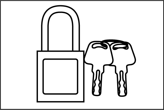 |
Insulating lock |
For protecting the plug and preventing electric shock |
|
8 |
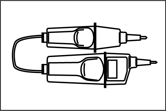 |
Voltage tester |
For checking voltage of high-voltage components |
Power-off of high-voltage electrical system 3D animation demonstration
-
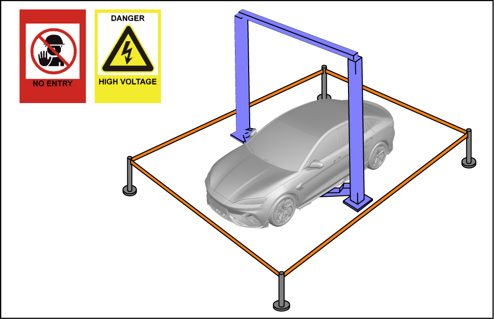
Drive the vehicle to the repair site.
Reminder
-
Set up protective fences in the maintenance area and place high voltage hazard warning signs.
-
Only relevant personnel wearing personal protective equipment can enter the maintenance area.
-
-
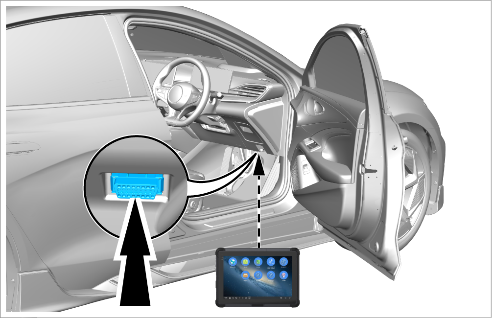
Read the DTCs of the battery execution and sampling unit with the VDS, and check for "sintering" fault codes such as main contactor sintering fault, voltage divider contactor sintering fault, and negative contactor sintering fault. If no such DTC is found, proceed to the next step. If any of them is present, troubleshoot the contactor sintering fault.
-
Disconnect all charging/discharging cables of the vehicle.
-
Fully lower all windows and unlock all doors.
CautionThis help to avoid trapping of maintenance personnel inside the vehicle and glass damage after the doors lock automatically.
-
Power off the vehicle.
-
Power off the low-voltage electrical system. Refer to Power-off and power-on of low-voltage electrical system
-
Open the hood.
-
Remove the left trim panel assembly of front compartment. Refer to Removal and installation of left trim panel assembly of front compartment
-
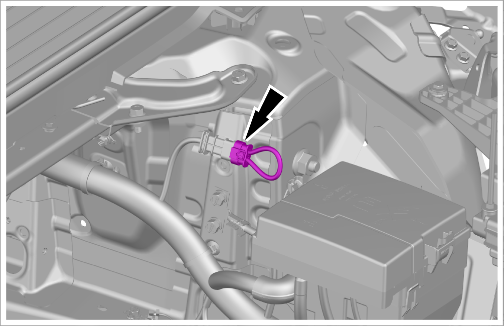
Disconnect the low-voltage service switch and keep the hood open.
Caution-
When the vehicle is undergoing repair of high-voltage components in a 4S store, or when there is a risk of electric shock due to abnormalities (such as collision and fire), it is necessary to disable high-voltage power. To facilitate disabling of high-voltage power, a low-voltage service switch should be added to the high-voltage system and connected in series in the high-voltage interlocking circuit.
-
During removal of the low-voltage service switch, press and hold the female terminal of its connector to pull it out. Do not pull the wiring harness at the end of the connector.
-
After disconnecting the low-voltage service switch, wait for 5 min, measure the disconnected high-voltage connectors or the high-voltage parts exposed after removing the maintenance port cover, and carry out high-voltage operation only when the voltage between the positive and ground, negative and ground, positive and negative is lower than 60 V DC or 30 V AC.
-
-
Remove the front subframe mudguard assembly. Refer to Removal and installation of front subframe mudguard assembly
-
Remove the battery pack anti-collision bar assembly. Refer to Removal and installation of battery pack anti-collision bar assembly
-
Remove 2 fixing bolts, and disconnect the front drive motor control unit wiring harness subassembly from the high-voltage battery system.
-
Tightening torque: 9±1 N•m
CautionAfter the high-voltage component is removed, timely sealing and insulation treatment should be carried out to prevent dust and impurities from entering or electric shock due to accidentally touching the high-voltage terminal.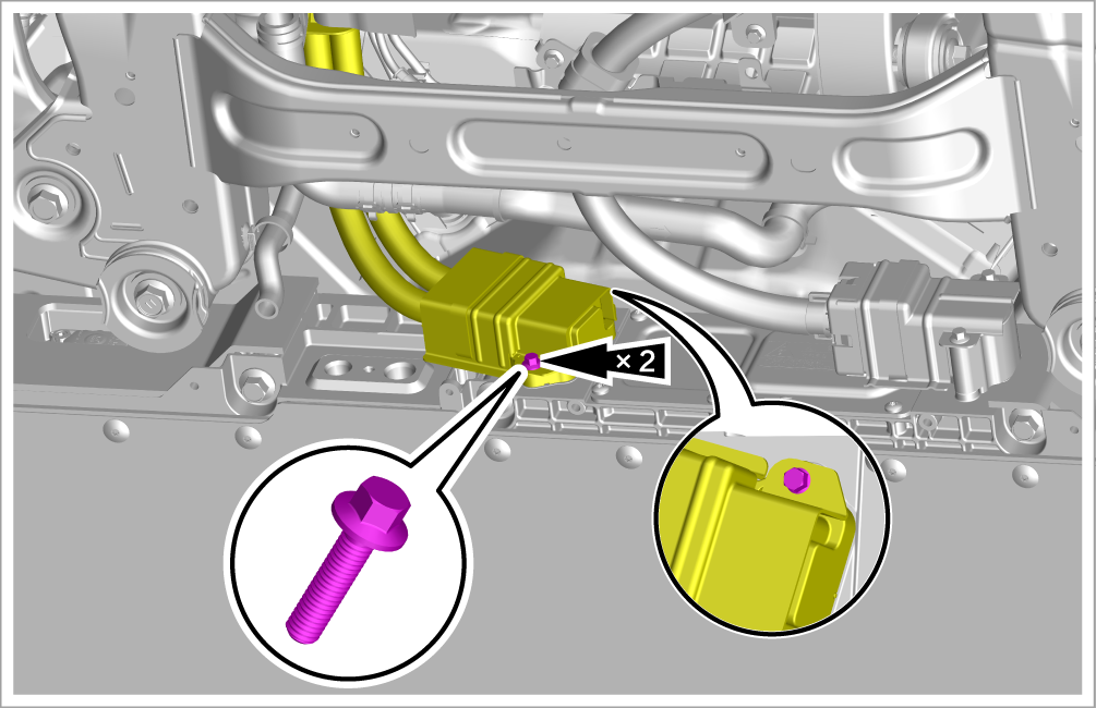
-
-
Measure the voltage of the positive and negative poles at the front end of the high-voltage battery with a voltage tester, and the voltage should be lower than 60 V DC or 30 V AC, within the safe voltage value range.
ReminderThis step is applicable to 4WD models.
Caution-
After measurement, timely sealing and insulation should be carried out to prevent dust and impurities from entering or electric shock due to accidentally touching the high-voltage terminals.
-
If the voltage of the connector terminals are all within the standard range, the high-voltage electrical system of the vehicle has been successfully powered off.
-
If the voltage of the terminals exceed the standard range, be sure to eliminate the fault. It is not allowed to repair any component of the high-voltage system until the fault is eliminated.
-
-
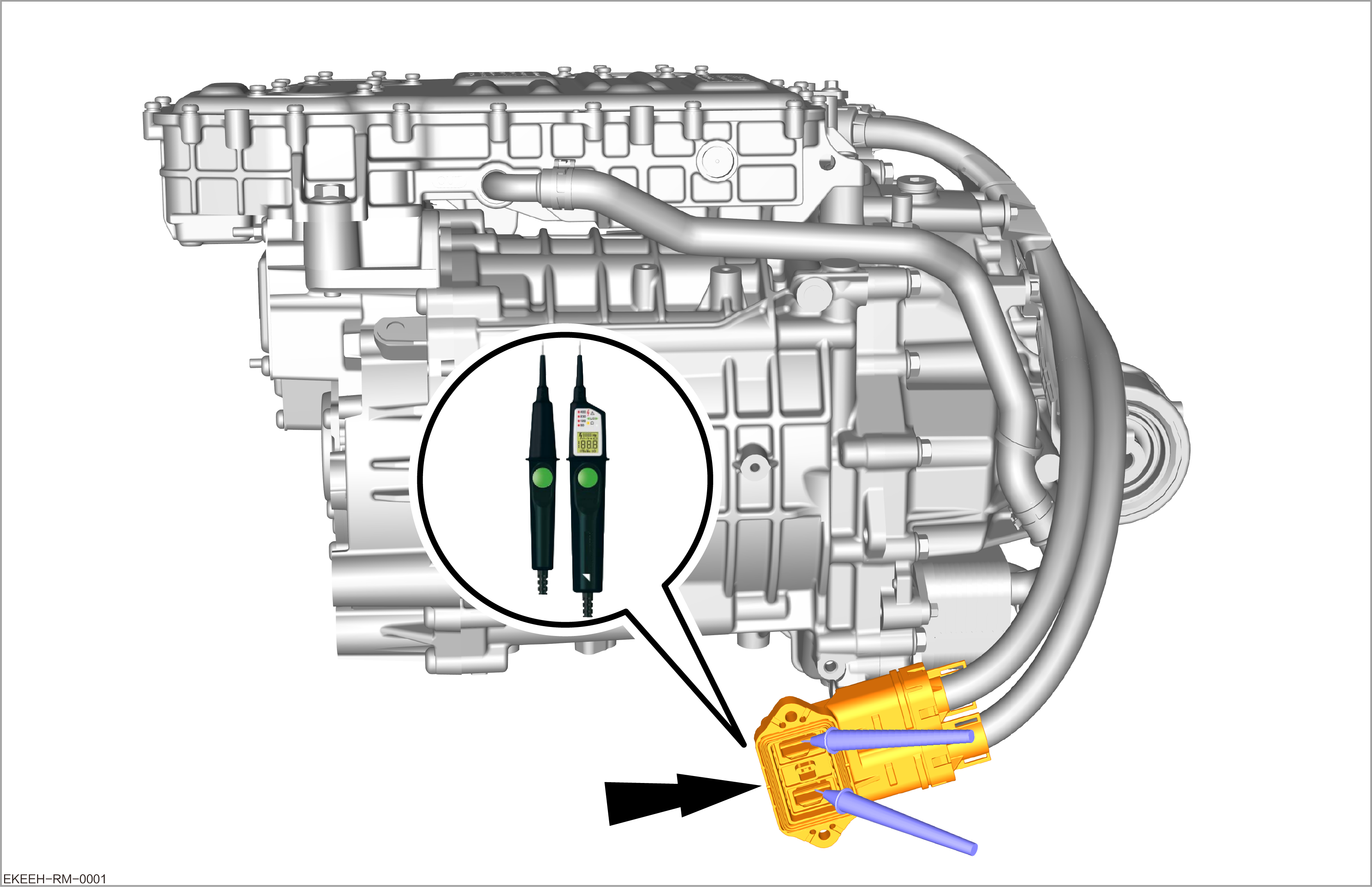
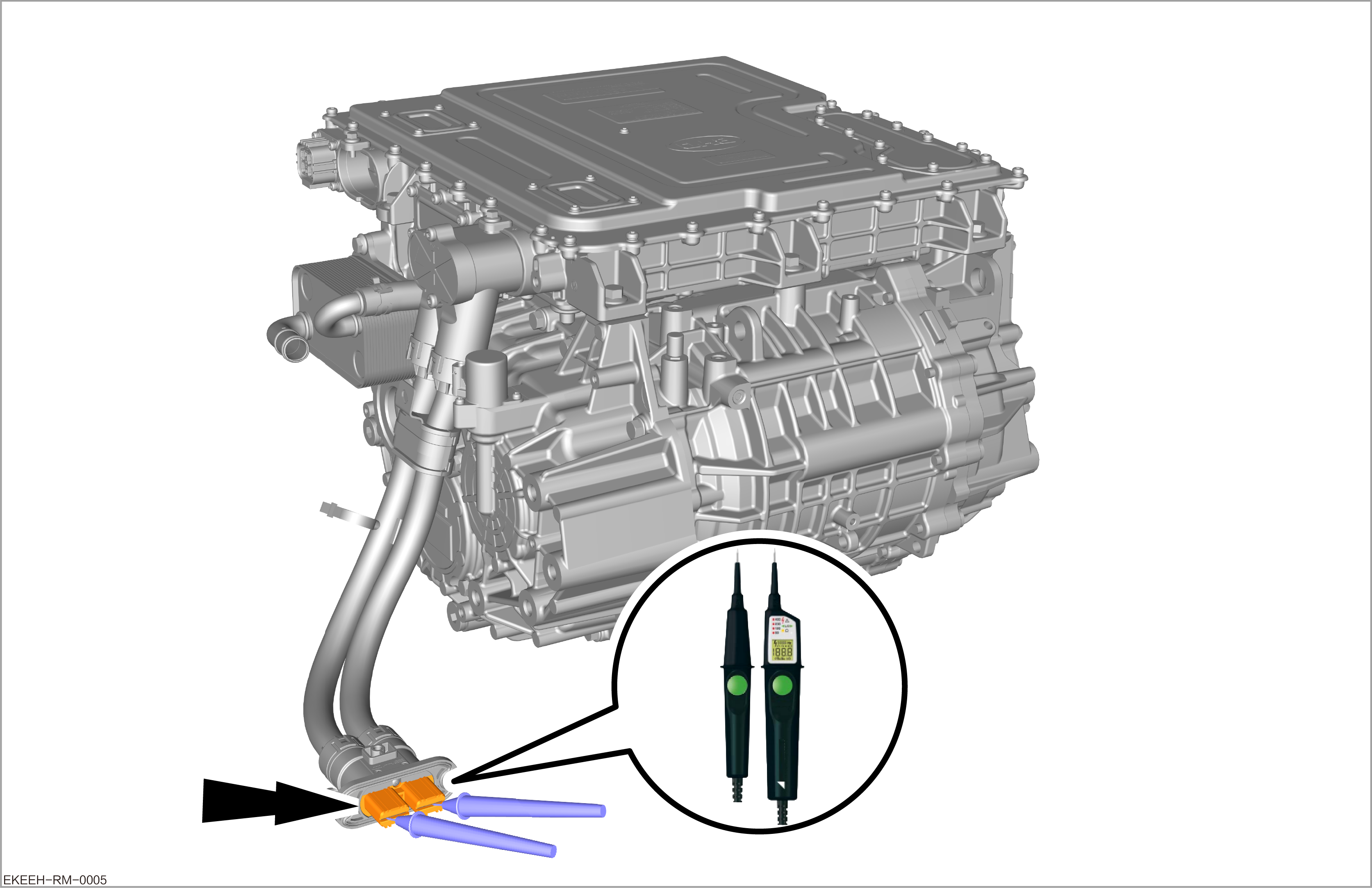
Measure the voltage of the positive and negative poles at the wiring harness of the front drive motor control unit with a voltage tester, and the voltage should be lower than 60 V DC or 30 V AC, within the safe voltage value range.
ReminderThis step is applicable to 4WD models.
Caution-
After measurement, timely sealing and insulation should be carried out to prevent dust and impurities from entering or electric shock due to accidentally touching the high-voltage terminals.
-
If the voltage of the connector terminals are all within the standard range, the high-voltage electrical system of the vehicle has been successfully powered off.
-
If the voltage of the terminals exceed the standard range, be sure to eliminate the fault. It is not allowed to repair any component of the high-voltage system until the fault is eliminated.
-
-
Remove the rear subframe mudguard assembly. Refer to Removal and installation of rear subframe mudguard assembly
-
Remove 2 fixing bolts, and disconnect the high-voltage distribution wiring harness subassembly from the high-voltage battery system.
-
Tightening torque: 5±0.5 N•m
CautionAfter the high-voltage component is removed, timely sealing and insulation treatment should be carried out to prevent dust and impurities from entering or electric shock due to accidentally touching the high-voltage terminal.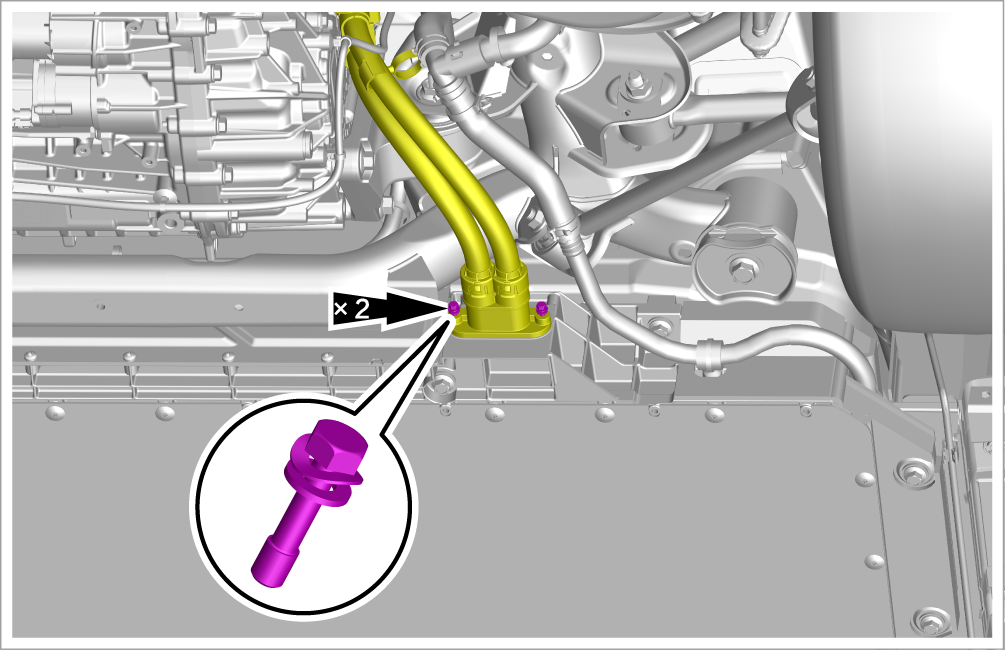
-
-
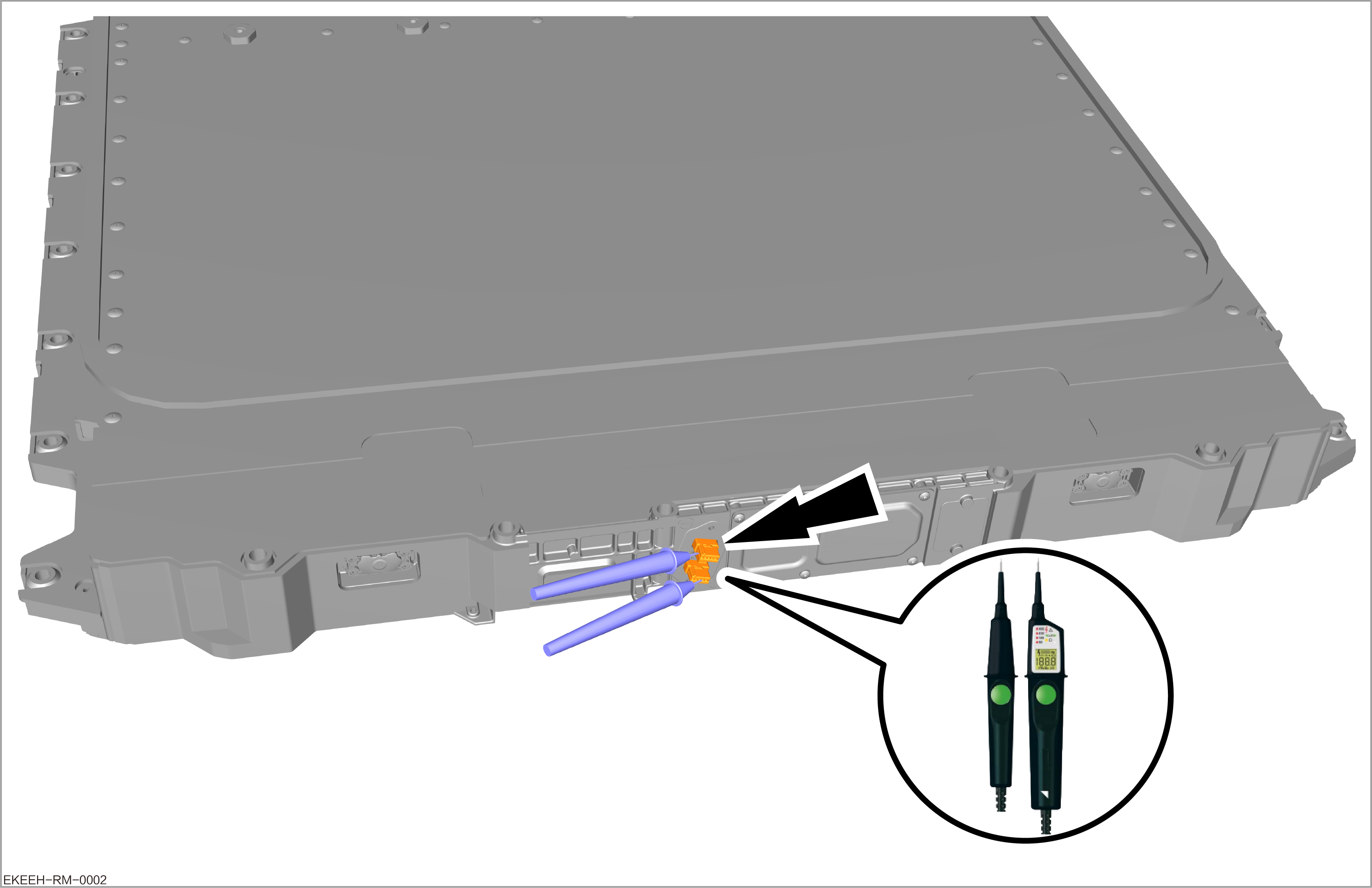
Measure the voltage of the positive and negative poles at the rear end of the high-voltage battery with a voltage tester, and the voltage should be lower than 60 V DC or 30 V AC, within the safe voltage value range.
Caution-
After measurement, timely sealing and insulation should be carried out to prevent dust and impurities from entering or electric shock due to accidentally touching the high-voltage terminals.
-
If the voltage of the connector terminals are all within the standard range, the high-voltage electrical system of the vehicle has been successfully powered off.
-
If the voltage of the terminals exceed the standard range, be sure to eliminate the fault. It is not allowed to repair any component of the high-voltage system until the fault is eliminated.
-
-
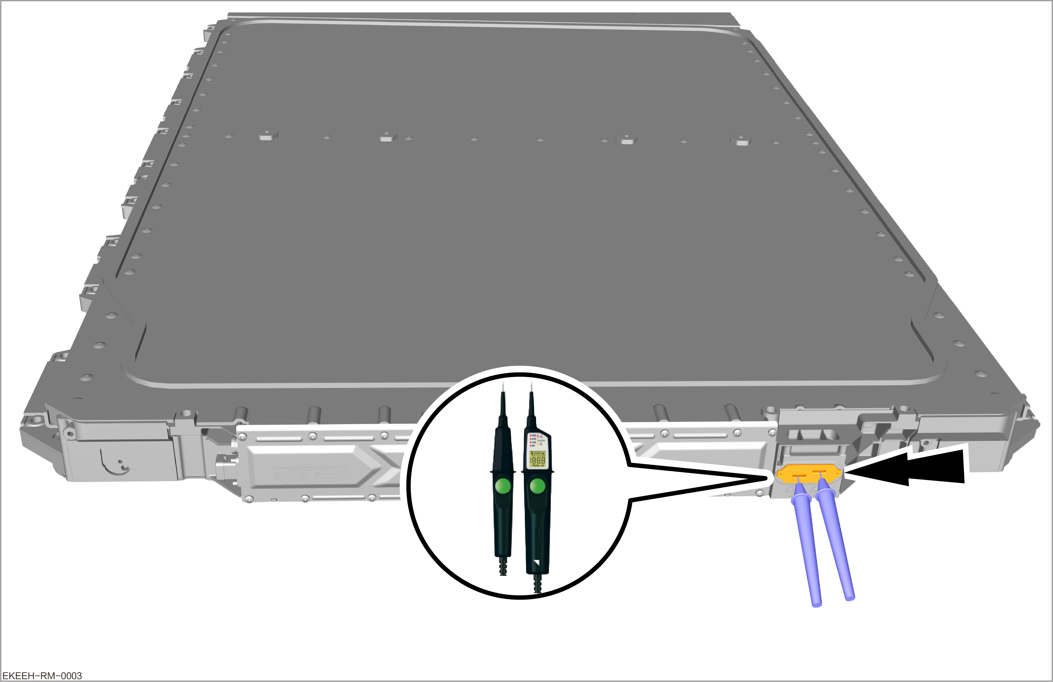
Measure the voltage of the positive and negative poles at the wiring harness of the high-voltage distribution wiring harness subassembly with a voltage tester, and the voltage should be lower than 60 V DC or 30 V AC, within the safe voltage value range.
Caution-
After measurement, timely sealing and insulation should be carried out to prevent dust and impurities from entering or electric shock due to accidentally touching the high-voltage terminals.
-
If the voltage of the connector terminals are all within the standard range, the high-voltage electrical system of the vehicle has been successfully powered off.
-
If the voltage of the terminals exceed the standard range, be sure to eliminate the fault. It is not allowed to repair any component of the high-voltage system until the fault is eliminated.
-
Power-on of high-voltage electrical system

AC ≥ 30 V and DC ≥ 60 V are lethal.
Electric shock or electric arch may cause death or serious injury.
-
Wear clothes that have passed the electric arc test.
-
Wear a helmet with face protection.
-
Wear protective insulating gloves.
-
Wear safety shoes
-
Connect the high-voltage distribution wiring harness subassembly to the high-voltage battery system, and install 2 fixing bolts.
-
Tightening torque: 5±0.5 N•m
-
-
Connect the front drive motor control unit wiring harness subassembly to the high-voltage battery system, and install 2 fixing bolts.
-
Tightening torque: 9±1 N•m
-
-
Install the low-voltage service switch.
-
Power on the low-voltage electrical system. Refer to Power-off and power-on of low-voltage electrical system
-
Install others in the reverse order of removal.
-
After all the circuits of the high-voltage electrical system and low-voltage electrical system are connected, power on the vehicle (OK mode), and check that the electric appliances of the vehicle are functioning normally and the vehicle is running properly. At this time, the high-voltage electrical system of the vehicle has been powered on.